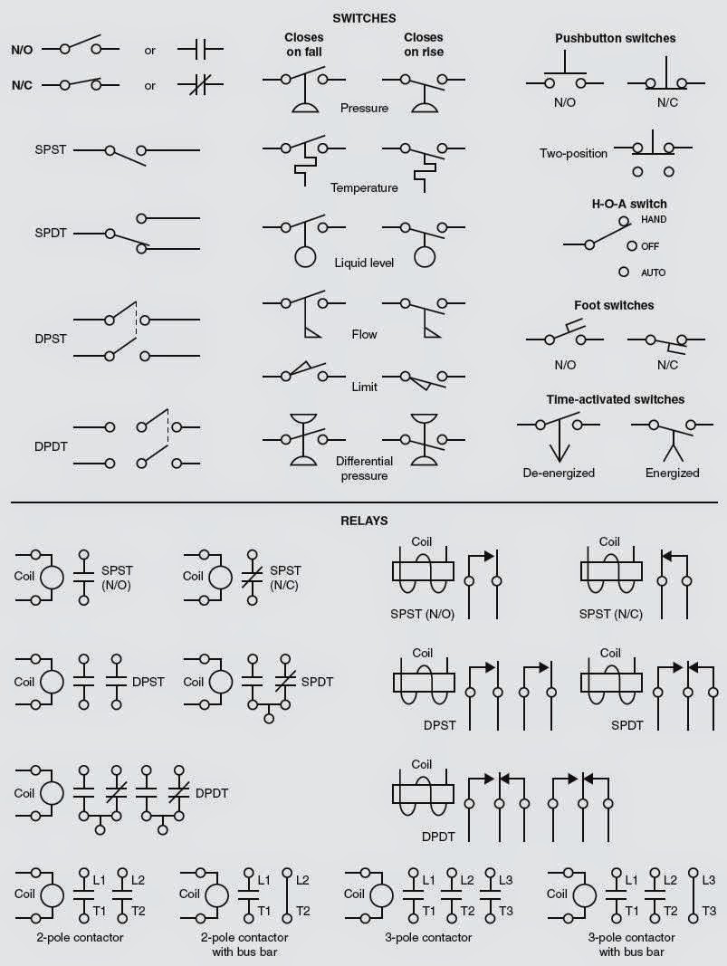
[diagram] logic control diagram symbols Schematic drawing symbols Electrical symbols
PLC program example with toggle or flip-flop function | Ladder logic
Logic symbols basic diagrams engineering gate symbol instrumentationtools figure Control logic gates in computer organization Logic structure diagram of control system
Circuit breaker symbol single line diagram
Block diagram of the control logic.Logic gates geeksforgeeks What is ladder diagram?Circuit logic analog digital symbols diagram circuits function integrated engineering components.
Tuning a pid regulatorGambar electrical wiring diagrams air conditioning systems part knowhow The basics of process control diagrams – technology transfer servicesControl logic circuit is used to allow only one cycle of the saw-tooth.

Circuit diagram
Electrical symbols diagram logic digital analog engineering wiring schematic library conceptdraw generator symbol drawing circuit schematics electronic pic diagrams industrialLogic control gates circuit gate computer architecture inputs javatpoint wired Diagram logic control block whats difference between drawing simulink transform diagaram matlab wiring math strip captur kb paintingvalley researchgate postLogic gate symbols diagram electrical diagrams wiring engineering elements draw examples conceptdraw library schematic drawing alu boolean bit template pic.
Ladder logic schematicHow to read a plc schematic « (2023) Whats the difference between control logic diagram and block diagramUnderstanding substation single line diagrams and iec 61850 process bus.

Logic structure diagram of control system
Control system: a control system logic diagram; b the electricalThe schematic diagram of the control logic Control logic gatesPlc program example with toggle or flip-flop function.
Logic diagram of the control system.Symbols logic diagram iec substation line single relay diagrams electrical bus engineering comparison sld utilities protection has understanding circuits depicting Block diagram of control logic section.New single line diagram symbols #diagram #wiringdiagram #diagramming #.

Circuit diagram gates
[diagram] master logic diagramLogic controller plc programmable diagram control architecture system process instrumentation output module component The logic diagram of control system.Diagram block control process system feedback diagrams basics flow figure drawing signals services technology.
Electrical symbols — logic gate diagramEngineering logic diagrams Plc(programmable logic controller)Ladder logic flip flop plc examples programming diagram toggle off button push function program circuit example coil control bradley allen.

Digital logic gates symbols
Logic symbols gates digital iec international electrotechnical commission electrical electronic which electricaltechnology german means stands .
.

![[DIAGRAM] Logic Control Diagram Symbols - MYDIAGRAM.ONLINE](https://i2.wp.com/www.edrawsoft.com/solutions/shapes/transmission-path-3.png)
[DIAGRAM] Logic Control Diagram Symbols - MYDIAGRAM.ONLINE

Whats the difference between control logic diagram and block diagram

Control Logic Gates | Computer Organization and Architecture Tutorial

What is Ladder diagram? - #2 by deepika45678 - PLC (Programmable Logic
Gambar Electrical Wiring Diagrams Air Conditioning Systems Part Knowhow

Block diagram of control logic section. | Download Scientific Diagram

Understanding Substation Single Line Diagrams and IEC 61850 Process Bus